The construction of an early experimental TV starts with the image mf.

The device was built in modules so that modules could be completely replaced during the experiments.

The image mf module had a receiver for channel 4. This is being built here.

Here the assembled channel 4 reception part.

The first image mf stage is ready and that of course gives the opportunity to test.

The test setup we use a Grundig VG1000 as a measuring transmitter modulated with gray scale black / white.

And this is how the black & white gray trap on modulated looks like on the scope.

If you add another section image mf. Does it look like this.

And on the scope it becomes much clearer. it is therefore an unmodulated video signal which is put on the carrier wave in am.

Here is the 3rd image mf stage mounted.

Here with the necessary tubes.

And then you find out that a tube has not been drilled.

Well... drill and ready extra hole and beyond.

After the demodulator is built some testing.

And that doesn't look like anything.

The demodulator circuit is mounted.

The top with the extra tube base.

Built the video amplifier but.....

The signal did not improve.

The definition of the video signal is just a drama.

But against that, the synchronization separator works fine.

Here you can see that there is something wrong with the video signal.

The assembled image mf module.

The top of the assembled image mf module.

The shaky signal but the solution was suddenly there...

An incorrect resistance value threw a spanner in the works all along.

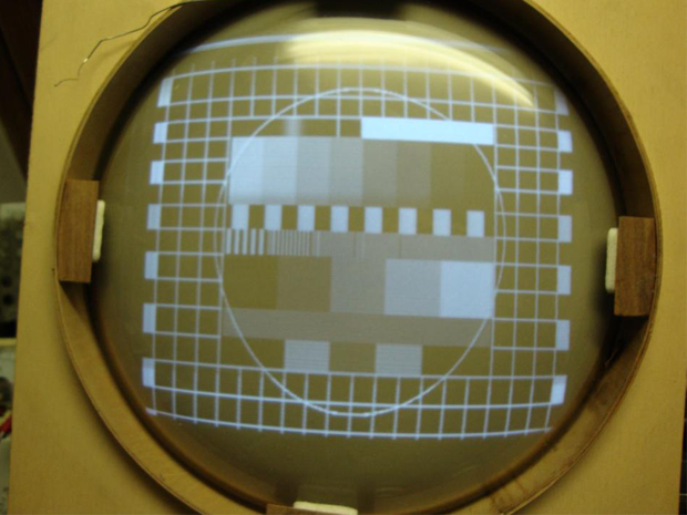
Now it looks good and even color.

OK then it's time to build the sound module.

The input stage of the first audio mf.

The bandpass filter between the first and second audio mf stage.

The stuff mechanically mounted.

The connections to the bandpass filter.

The construction of the detector.

The detector is built around the EQ80 tube, here the detector coil.

Detector coil mounted.

The EQ80 has been used for a short time and works according to the quadrature detection principle. This is used to demodulate FM with phase shift.

The detector circuit is complete.

The measurement setup.

The two high-frequency signals are phase shiftable.

Almost the 180 degree shift.

Almost no shift.

FM signal.

The circuit.

Here are some measurements on the detector. Here the carrier wave modulated with 50Hz in FM

Carrier wave modulated at 200 Hz in FM.

Carrier wave modulated at 600 Hz in FM.

Carrier wave modulated at 1 KHz in FM.

Carrier wave modulated at 5 KHz in FM.

Carrier wave modulated at 10 KHz in FM.

Carrier wave modulated at 15 KHz in FM.

Carrier wave modulated with no signal in FM.

The measurement setup.

The complete sound module top.

The complete sound module bottom.

Now comes the fun measuring on both image and sound receiver.

Channel 4 in provides demodulated audio and video.

sound detector.

A test around the vertical sync pulse.

With a time delay setting of the scope you can see why sometimes the sound rattles. In this case, a rattle occurred at the frame sync pulse. Here it is reduced to a minimum.

Both modules next to each other.

The power supply because the filament of the tubes are connected in parallel you need a huge power supply transformer.

The structure of the power supply.

Power supply mounted and working. Equipped with plug socket connections for experimental purposes.

The other view of the power supply.

The underside of the power supply.

The deflection and the high voltage.

There are 3 circuits located on this module. The vertical deflection. The horizontal deflection. And the high voltage.

The experimental character lies in the fact that the high voltage runs at 1Khz and is not part of synchronization. This was done in order not to redesign the entire device in the event of a broadcast standard change.

Later, the same principle was applied to multi-standard monitors such as computer monitors.

Here the first tests with the horizontal oscillator.

Here's a view of the horizontal oscillator.

Because I didn't have a correct horizontal deflection transformer I did some tests with a line transformer.

The horizontal deflection transformer is in the tin on the right, what you see here in the photo. This can is empty and we will see it later.

The horizontal steering pulses.

Measured on the anode of the EL34.

The setup is a loose line transformer with a loose deflection yoke attached to it for load.

Another frequency measurement.

Just a frequency measurement to see if we reach 15.625Khz

The loose line transformer.

The top of the whole.

Then we move on to the vertical deflection.

Here the blocking oscillator.

The construction of the vertical deflection.

The vertical deflection impulse. Again with load from the deflection yoke.

The test setup.

Another top view. At this point I didn't have a high voltage can yet.

Although I didn't have a high voltage can yet, I started building the circuit.

The circuit for the high voltage generator is on the left.

The components for the high voltage are on the chassis.

And when you come here you will think what is a TV without a picture tube.

Here the picture tube module. There is little to say about it, there is no more than a tube on it.

Then for the sake of beauty all modules separately together.

A side view but also....

A rear view....

A top view.

We have the high voltage can now we can test.

A kilovolt or 6 is enough for this picture tube.

Just an idea of the deflection generators and the high voltage.

And then it's time where we build the stuff into a chassis.

Put the chassis on the trestle and connect module by module.

The modules are connected to each other with a wire harness.

Here all modules mounted on the chassis.

Just connect the sound part.

Everything is on and on.

The question arises could it work.

We know that some loose parts work, but in a whole is still the question.

We still miss the horizontal deflection transformer, but that doesn't stop us from testing.

The grid saw works and to be able to see some image...

We just used a separate line transformer.

And now we don't have a focus control yet.

And here's the first slightly visible image.

Some tinkering with light dark contrast.

Some more tinkering.

This is how it looks with the separate line transformer.

The grid is a bit small and horribly distorted.

Some tinkering yields sufficient amplitude. Due to the loose character of the horizontal deflection, this has been omitted for a while.

The vertical deflection.

The light dark scheme.

A test with the horizontal deflection. It's not quite what you expect.

Wrap a new transformer.

The picture hmm...

The deflection pulses.

The test setup.

And well....

It's not working well you can say.

New horizontal deflection transformer.

The picture looks really good.

An overview of the whole.

The pulses.

The damping diode it really burns.

The transformer

The image looks good, no weird bumps.

The transformer works well enough. Time for installation.

The transformer here in the tin ready for pouring.

The transformer molded into the can.

On the chassis.

And image wow it finally works.

An overview image and chassis.
And for the enthusiast image and sound. An experimental television completely rebuilt.

The example of which the television has been recreated. This is an early experimental television that has been used for all kinds of testing. This device was never marketed.